Manipulating Frictional Performance of Wet Clutch Engagement through Material Properties and Operating Conditions


School of Automotive Engineering, Kookmin University, 77 Jeongneung-ro, Sungbuk-gu, Seoul 02707, Korea
Lubricants 2022, 10(9), 225; https://doi.org/10.3390/lubricants10090225
Submission received: 22 August 2022
/
Revised: 13 September 2022
/
Accepted: 15 September 2022
/
Published: 19 September 2022
(This article belongs to the Special Issue Automotive Tribology II)
Abstract
:Wet clutch engagement is mainly influenced by the frictional behaviors between the friction pad and steel plate as well as the lubrication behaviors. A positive μ–V friction coefficient of the wet clutch pad is the most preferable characteristic for improving antishudder behavior. In this study, a wet clutch engagement mechanism is theoretically divided into two major frictional behaviors, namely, direct asperity contact of interacting surfaces and hydrodynamic lubrication, for positive μ–V friction performance. These two behaviors are investigated with regard to both material characteristics of the friction pad–steel plate interactions and hydrodynamic lubrication mechanism. Frictional interactions of the friction pad are analyzed according to the material properties of the friction pad, such as elasticity, permeability, and roughness. Hydrodynamic lubrication, by which the initial period of the engagement is dominantly governed by the waviness of surface shape, is investigated to increase the frictional resistance in the initial stage of engagement relative to that in the final stage of engagement for realizing a positive μ–V friction coefficient. Computational simulations of wet clutch engagement behaviors are performed and compared with each other to obtain positive μ–V friction characteristics of the friction pad.
1. Introduction
Wet clutch engagement is a combinational friction behavior of direct contacts and hydrodynamic lubrication involving squeezing and sliding movements between frictional surfaces. The friction pad of the wet clutch material has unique characteristics such as contrasting permeability compared with that of the steel surface, which is impermeable to lubricants, and its high softness makes its elasticity another influencing material parameter in the engagement performance of the wet clutch. Torque transfer in the wet clutch mainly occurs by the direct surface contact between the friction pad and steel plate, which is the frictional action of asperity interactions on the surfaces. Therefore, torque transfer during wet clutch engagement should be investigated with respect to various material parameters and movements of the surface contact.
Gao et al. [1] simulated wet clutch engagement and torque response to determine the effects of several parameters of the friction pad and working conditions using the one-dimensional Reynolds equation model of a grooved paper-based clutch pad. Some parameters were found to be dependent on others, and friction characteristics were closely related to surface roughness and fluid viscosity.
Moreover, Wenbin et al. [2] investigated the effects of material parameters and working conditions on the engagement of a carbon fabric wet clutch. They divided the clutch engagement process into three stages: hydrodynamic, boundary, and mechanical contact. Several parameters in the simulation of wet cutch engagement were conditioned to match the experimental results.
Further, Zhang et al. [3] simulated a dynamic friction coefficient model of a wet clutch, with experiments involving working conditions and clutch pad material parameters such as permeability, elasticity, applied load, and lubricant viscosity. In their work, friction pad permeability and lubricant viscosity were found to be major influencing parameters in the wet clutch engagement.
The friction coefficient between the wet clutch pad and steel plate during the engagement is very crucial for shudder avoidance. Positive μ–V characteristics of friction between the friction pad and steel plate are essential to achieve optimal shudder behavior during the torque transfer of the wet clutch due to the positive damping effect, whereas most frictional behaviors undergo negative μ–V phenomena [4,5,6,7,8].
The positive μ–V characteristics of the wet clutch pad can be formulated with related material properties and operating conditions, which is contradictory to the negative μ–V characteristics of friction behavior. However, positive μ–V characteristics of the wet clutch pad are achievable through the combination of material properties and operating conditions [9,10]. In particular, the permeability of the friction pad is the most uncommon characteristic of the frictional surface because the lubricant permeates into the contacting surface. Along with the elastic deformation of the friction pad by the applied load, hydrodynamic lubrication is increasingly activated in the initial stage of engagement by increasing the frictional torque during the engagement. Permeability due to the addition of some material ingredient such as carbon is related to the elastic modulus [10]. Moreover, surface roughness on the frictional surfaces on both friction pad and steel plate is the main property in the final stage of wet clutch engagement [11,12].
Wet clutch engagement involves three processes, namely, hydrodynamic lubrication, boundary lubrication [13,14], and direct mechanical asperity contacts in sequential order [2,3,15]. The clutch contact is generally a two-dimensional surface contact that contains surface patterns or geometrical height variations. Thus, to achieve good correlation between simulation and experiment, two-dimensional surface contact formulation is required [15,16,17,18]. Further, material parameters of the wet clutch pad and operating conditions have been formulated using numerical methods [3,7,16,19]. A pattern groove may also be considered to have better cooling performance for removing frictional heat that sensitively effects the friction performance [20]; however, the groove patterns reduce the size of the contact area. The contact surface geometry of the friction pad is another influencing parameter for controlling the torque transfer mode. The unstable negative μ–V friction as a function of contact velocity, time, and displacement is a major cause for the stick–slip vibration in the wet clutch engagement. The friction characteristics of the wet clutch engagement depend on the properties of friction materials, such as elasticity, permeability, surface roughness, lubricant viscosity, and operating conditions such as applied load and rotational speed. The key parameter for predicting the engagement performance of the wet clutch is the friction coefficient as a function of relative sliding velocity [1,3,5].
In this work, frictional torque transfer is shown to have a control mode that has positive μ–V characteristics for reduced shudder during the wet clutch engagement. Numerical results shows that a geometrical shape of waviness of the friction pad generates strong hydrodynamic pressure development caused by the wedge effect in addition to squeeze film effect with full two-dimensional analysis. Material parameters such as permeability, elasticity of the friction pad, and lubricant viscosity as well as geometrical contact shape of the friction pad, such as waviness, are also shown to provide equivalent positive μ–V frictional torque transfer.
2. Characteristics of Wet Clutch Engagement
In the initial stage of wet clutch engagement, the lubricant undergoes squeeze motions due to the applied load and then shearing due to the relative sliding velocity between the friction pad and steel plate. Shearing of the lubricant generates viscosity resistance to enable torque transfer. If the two contact surfaces have a geometrical slope with respect to each other, a large hydrodynamic pressure is generated and helps to enlarge the viscosity resistance. After this initial stage of the engagement, the two surfaces of the friction pad and steel plate get closer to each other and then come into contact with the existence of a lubricant film in the gap. The clutch pad surface has a designed roughness that helps to generate appropriate friction behavior that functions to provide high torque transfer. Therefore, in order to have fast and soft torque transfer during the engagement under the applied loading condition, combinational behaviors of the shearing fluid film layer according to the viscosity of the lubricant and direct contact between the friction pad and steel plate should be managed to realize the desired torque transfer.
Depending on the effects of material parameters of the friction pad, operating conditions, and lubricant viscosity characteristics, the torque transfers due to the lubricant viscosity and clutch pad material properties have various modes that reveal the frictional behaviors in the engagement of the wet clutch, such as positive and negative μ–V characteristics. Soft engagement, which reduces shudder phenomena in the wet clutch system, is possible by realizing a positive μ–V friction mode between the friction pad and steel plate, whereas most frictional behaviors have negative μ–V friction modes where static friction is greater than dynamic friction. In the wet clutch system, management of frictional behaviors from direct contact of the clutch pad surface and steel plate, as well as viscosity shear resistance due to hydrodynamic lubrication, should have positive μ–V mode. Therefore, the friction coefficient in terms of transferred torque in the wet clutch system can be realized to have positive μ–V characteristics.
A unique characteristic in wet clutch friction mechanisms is that fluid lubricant smears onto the porous clutch pad and the lubricant slips on the clutch surface, which is not the general lubrication boundary conditions on fluid–solid interface such as no-slip boundary condition on a steel plate. Permeability of the wet clutch pad influences hydrodynamic lubrication performance, particularly at the initial stage of engagement when the squeezing movements and relative sliding velocities of the clutch pad and steel plate are very large. In this stage, the viscosity shear resistance due to the hydrodynamic lubrication generates a large viscous torque and provides a relatively large dynamic friction mode. Moreover, the material property of permeability in the clutch pad can increase the hydrodynamic lubrication effect such that low permeability makes the lubricant film laid on the friction pad surface delay the engagement [1,2,3,9].
The small elastic rigidity of the clutch pad material deforms the clutch pad surface easily, when the applied load initiates contacts between the clutch pad and steel plate. The Young’s modulus affects the torque transfer and engagement period such that the low rigidity of the clutch pad generates a high friction torque via the squeeze film effect, due to a large elastic deformation [1,18,21].
The surface asperity of the clutch pad deforms and a rough surface results in a thicker average film gap than the smooth surface. Therefore, a higher torque is generated with a smooth surface than with a rough surface in the initial stage of engagement [1,3,5].
Lubricant viscosity is another influencing parameter during the wet clutch engagement in both hydrodynamic lubrication at the initial stage and boundary lubrication mechanism at the final stage of engagement. In this work, boundary lubrication behaviors are not considered because they are the chemical reactions between the lubricant additives and friction pad surface [13,14]. Therefore, viscosity of the lubricant is assumed to be a Newtonian fluid that is not influenced by the shear rates of lubricant film behaviors. Only bulk viscosities are compared in the computations of clutch engagement. A higher viscosity generates a large torque transfer due to the shear resistance of the lubricant film and increases the engagement time [1,2,3]. However, recently adopted lubricants in powertrain systems have low viscosities due to the energy efficiency, which shortens the endurance life in the contact-driving modules of the system. This contradictory mechanism between long endurance life and high energy efficiency should be managed with module system design development. That is, the endurance life problem due to low viscosity of the lubricant can be managed using shape design of the friction pad, e.g., groove patterns and waviness on the friction pad.
3. Modeling of Wet Clutch Frictional Pad
A wet clutch has the shape of a circular band and has rotational movement. The fluid behavior in the gap between the friction pad and steel plate is under centrifugal force and is expressed by the following equations in radial and circumferential directions:
The fluid velocity in the circumferential direction is derived from Equation (1):
The wet clutch contact mechanism is shown in Figure 1 and Figure 2. The steel plate has no-slip boundary condition of the lubricant fluid on its surface, whereas the lubricant slips on the friction pad surface, into which it permeates as well [21]. The velocity slip condition is imposed on the clutch pad surface in the radial direction. The flow in the clutch pad of porous media is modeled as a Darcian flow and its pressure gradient is considered constant [3,21].
Using Equations (4) and (5), the slip boundary condition [9] is applied on the friction pad surface in the radial direction:
Equations (3)–(5) provide the velocity component in the radial direction .
The Darcian flow in the friction pad of the porous material and its elastic compression are included with the squeezing and sliding movements. In the squeeze direction, the friction pad undergoes elastic deformation due to its soft material characteristics compared to the steel surface. Here, the asperity contact pressure on the friction pad surface is computed according to the applied hydraulic load [3]. The continuity equation integrating the velocity components in radial, circumferential, and squeezing directions across the film thickness is applied to satisfy the mass conservation law. Then, the two-dimensional modified Reynolds equation can be derived.
The surface roughness on the friction pad surface (Ra = ~4.0 μm) is the dominant parameter compared to the lubricant film thickness scale and its pattern is considered isotropic. The surface roughness on the steel plate is considered smooth owing to its small value (~0.1 μm) compared to that of the friction pad. The lubricant film thickness represented by the average gap with a Gaussian density function of rough surface is shown by Greenwood and Williamson [22].
As the relative rotational velocity becomes zero and the applied load approaches the desired level by the applied hydraulic pressure (~6.5 bar), the fluid film thickness decreases. However, the fluid film exists even when the relative rotational speed becomes zero under the desired hydraulic load because the surface roughness supports the applied load. Therefore, surface roughness should be considered an input design parameter in the computation of wet clutch engagement. The surface roughness pattern, which affects the fluid film pressure, is included by the formulation of a pressure factor [23,24].
Asperities on the rough surface come in contact with the counter surface of the steel plate and support the applied load with hydrodynamic film pressure. The asperity contact pressure can be described by parameters such as number of asperities per unit area , asperity tip radius , and rms roughness [23].
where is the probability density function of . Therefore, the asperity contact pressure per unit area with elastic modulus for the contact material is
After all the influencing parameters are considered, the two-dimensional modified Reynolds’ equation can be derived using the pressure flow factor [23,24].
Equation (10) includes all the material parameters of the clutch pad and lubricant, such as permeability, elasticity, roughness, slip coefficient, and viscosity, on the two-dimensional surface in the radial and circumferential directions. Although solving the two-dimensional modified Reynolds’ equation is very complicated, it can provide complete information on fluid film behaviors in the gap between the wet clutch pad and steel plate, including the effects of surface geometrical shape [16,17,18,20]. By contrast, many other studies simply analyzed the one-dimensional domain in the radial direction for simplicity. One-dimensional computation in the radial direction of the modified Reynolds’ equation can be performed in a fast and easy computation mode, but it cannot give any information on the fluid film pressure variations in the circumferential direction [1,2,3,7,19].
The modified Reynolds’ Equation (10) is solved by the finite difference method regarding the unknown value of hydrodynamic pressure . The finite element method [18,21] that has more freedom of degree on the mesh generation is also applicable but convergence is less stable than in the finite difference method. In order to obtain the value of , other values in this equation should be set to be known. An initial guess for the film thickness h needs to be set at first and other values such as flow factors of surface roughness, permeability, geometrical gap, and sliding velocities of both friction pad and steel plate are given to Equation (10) at each time step appropriately according to the related modeling equations and values in Table 1 and Table 2. The mesh size over the friction pad area is about 481 in the circumferential direction, 21 in the radial direction, and 31 in the axial direction with equidistant mesh size. The convergence criterion for the hydrodynamic pressure is 0.05% at each time step with the SOR numerical method. With the time step of 1.0 ms that the convergence stability for solving Equation (10) delicately depends on, the hydrodynamic reaction force is obtained by integrating the hydrodynamic pressure over the friction pad area. With the given film thickness at each time step, the asperity contact pressure, Equation (9), is calculated and integrated over the friction pad area to obtain the mechanical contact load.
In this work, the geometrical wavy surface structure of the friction pad is included to precisely verify how the hydrodynamic lubrication effects occur during the engagement and relate to the engagement behaviors of torque transfer in terms of friction coefficient. If the contact surfaces are flat against each other, then the hydrodynamic pressure occurs only when squeeze motion does. Therefore, the hydrodynamic pressure due to geometrical shapes such as waviness or groove patterns additionally changes the engagement mode to provide μ–V characteristics during the initial stage of engagement.
Many other studies investigated simple one-dimensional analysis [1,2,3] for fast computation of frictional torque transfer and compared to other experimental work [2,3,6,7,9,10,19]. Few two-dimensional studies [16,17,18] investigated the full hydrodynamic pressure developments that provide the favorable torque transfer performance. Additionally, they did not point out the mechanism that enhancement of hydrodynamic pressure development at the initial stage of wet clutch engagement can provide positive μ–V characteristics.
Once the hydrodynamic film pressure is obtained from Equation (10), the force balance between the applied force W(t) and total reaction forces from both hydrodynamic and asperity contact pressures should be checked. Both the reaction forces depend on film thickness. However, hydrodynamic pressure needs to be computed using the film thickness h(t) as well as its time step rate due to the squeeze motion given in Equation (10) (Figure 3):
Frictional torque from both viscous fluid behaviors and asperity contacts friction was computed, and at the same time, the relative rotational velocity of the friction pad in the steel plate was calculated according to the time step with the clutch system inertia.
Viscous torque due to the hydrodynamic lubrication behaviors was calculated (Figure 4) from the shear stress on the friction pad surface with the stress factors [11,12].
Frictional torque due to asperity contact is computed using Equation (13):
Where fc is the friction coefficient of the mechanical asperity contact, which generally depends on the sliding velocity. One method to obtain the friction coefficient is by curve fitting of experiment results [1,2,9]. In general form, static friction coefficient is greater than dynamic friction coefficient . Depending on the magnitudes of constants and of Equation (14), the torque transfer mode is revealed in either positive or negative μ–V characteristics [1,3,4,16,20] together with the torque transfer behavior by the hydrodynamic lubrication in the initial stage of engagement. Some studies [3,15] have regarded the friction coefficient of the mechanical asperity contact as a constant boundary friction value. In this case, the hydrodynamic lubrication effect can clearly generate positive μ–V characteristics, leading to favorable vibration performance of the wet cutch system.
In this work, the boundary friction coefficient, which indicates the mechanical asperity contact, is modeled to vary according to the sliding speed, that is, is larger than The friction coefficient form of the mechanical asperity contact in general negative μ–V mode is described by Equation (14):
The completion of the engagement process is marked by the relative velocity between the friction pad and steel plate becoming zero () owing to viscous and asperity contact torques; it can be described using Equation (15). The total engagement period depends on the influencing parameters, namely, viscosity and mechanical asperity contact torques, and inertia of the clutch system.
For the frictional behavior between the friction pad and steel plate to be managed, the abovementioned influencing parameters in the wet clutch engagement are adjusted in combination to achieve favorable μ–V friction characteristics. The wet clutch engagement according to the parameters of the base model is computed, and comparisons of positive μ–V characteristics designs with the base model are shown.
The wet clutch engagement of the base model is operated under the parameter conditions given in Table 1. The clutch pad shape of the base model is flat (Figure 5) and does not have any groove patterns on the friction pad surface. The major material properties of the friction pad considered in this work are elasticity, permeability, surface roughness of the friction pad, and lubricant viscosity. An applied pressure is imposed on the clutch pad surface with the following time variation:
Wet clutch engagement behaviors were investigated in terms of loading modes, torque distributions from asperity contact and hydrodynamic lubrication, film thickness, and relative rotational velocity variation as the time function of the engagement process (Figure 6). These output behaviors are sensitively influenced by the material properties of the friction pad, lubricant viscosity variation, and operating conditions.
An applied pressure is imposed on the clutch surface by a hydraulic actuator and saturates to a value of 6.5 bar with a time delay of t0 = 0.01 s in the base model computation. According to the mode of applied pressure (Equation (17)), the film thickness decreases (Equation (16)) and more mechanical contacts occur. Then, the frictional torque transfers due to both mechanical contact and the viscous shear resistance between the friction pad and steel plate occur in different variations depending on other material properties of the friction pad. The frictional torque due to mechanical contact starts as soon as the film thickness approaches the level of the surface roughness and viscous friction becomes lower as the relative velocity becomes zero. At the final stage of engagement, the torque transfer mode depends mainly on the friction coefficient of the mechanical contact, that is, the curve-fitting constant C1 and C2. In particular, C2 represents the rooster tail shape in the torque transfer mode from the mechanical contact. Many studies have considered different values of the constants according to the experimental curve-fitting data or constant values throughout the velocity range for simplicity [2,6,15]. In the base model, C1 and C2 are set to have a smaller than , because it needs to verify the influences of two major mechanisms: mechanical contact and hydrodynamic interactions in the frictional torque transfer modes during the engagement.
In this base model, viscous friction occurs mainly via the squeeze motion because a flat contact geometry cannot generate hydrodynamic lubrication pressure. Based on this mechanism, positive μ–V characteristics can be managed by enhancing the hydrodynamic effects through the shearing motion of the lubricant film at the initial stage of the engagement.
The reaction forces due to both asperity contact and hydrodynamic pressure during the engagement process are computed using Equations (8)–(11). In the base model case, the reaction force due to the hydrodynamic pressure is mainly provided by the squeeze motion because the friction pad surface is flat and smooth without any hydrodynamic pressure generation due to the wedge effect. Further, in the base model computation, hydrodynamic pressure occurs at the initial stage of engagement in a very short period and then disappears following the asperity contact pressure as the film thickness decreases. At this moment, the delay time t0 of applied pressure p(t) plays the main role in hydrodynamic pressure generation because the applied load mode determines the squeeze rate of the lubricant film.
Relative velocity becomes zero (Figure 7) as the engagement proceeds by solving Equation (15) and the film thickness approaches the saturated value depending on the surface roughness scale and applied load magnitude.
The friction coefficient variation of the friction pad on the steel plate according to the relative velocity can be obtained from the total torque transfer values during the engagement. It is the actual frictional coefficient according to the constant speed in the wet clutch engagement. The values of the equivalent friction coefficient are calculated using Equation (18) and are shown in Figure 8.
In the initial stage of clutch engagement (), the clutch surface is under severe squeeze motion with a thick film gap and large velocity relative to the steel plate. The equivalent friction coefficient should be very small at this moment because it is under pure hydrodynamic lubrication without any direct surface contact. However, its computed value is abnormally large at the very moment of engagement, as seen in Figure 8a. Then, it becomes smaller and subsequently increases up to the static friction condition. At this moment of starting the engagement, the contact behavior between the clutch pad and steel plate is under sliding as well as severe large squeeze motions. If the clutch pad is flat and without a groove pattern, shearing behaviors of the lubricant film provide friction resistance via only coquette flow without hydrodynamic pressure development. Hydrodynamic pressure development becomes small and then the direct contact follows between the friction pad and steel plate. It is an unavoidable mechanism in the engagement of the wet clutch system due to the large squeeze motion by the applied load in a very short period. By contrast, if there is a groove pattern or other geometrical shape on the clutch pad surface, the hydrodynamic lubrication pressure is much developed and viscous frictional torque has a greater influence on the torque transfer. According to this mechanism, the contact behavior at the starting moment of engagement shows that hydrodynamic lubrication can be managed to realize positive μ–V characteristics.
4. Parametric Computations of Wet Clutch Engagement for Positive μ–V Characteristics
Uncomfortable vibrations such as shudder or stick–slip behaviors in the wet clutch engagement can frequently be removed by realizing favorable slipping control. Shudder is caused by the combinational physical contact state between the friction pad and steel plate along with operating conditions and lubricant viscosity, among other factors. A positive μ–V property is a required condition for antishudder behaviors in a wet clutch system to remove self-excited vibration when transmitting torque between the friction pad and steel plate surfaces [4,6,7,8].
In this work, a positive μ–V friction mode based on combinational management of the friction pad properties, lubricant viscosity, operational loading condition, and surface shape design, etc. was derived for antishudder performance (modified base model).
Permeability in the friction pad material can be managed through the constituent materials such as carbon fiber [2] and other various resins in paper-based material structures. A large permeability indicates that the hydrodynamic lubrication pressure is less developed owing to the spread of the lubricant into the porous media; therefore, it provides fast direct surface contact to enable mechanical torque transfer [1,2,3]. Depending on the permeability characteristics, frictional torque from either hydrodynamic lubrication or direct mechanical contact can be managed.
However, soft elasticity of the friction pad material results in its greater deformation. This causes the squeeze velocity of the film thickness change rate to rise with time. Therefore, the hydrodynamic lubrication effect is more activated in the initial stage of engagement, which generates additional frictional resistance. Moreover, most studies have referred to the permeability effect as the point at which the fluid film cannot sustain the load capacity as soon as the applied load is imposed. Therefore, less hydrodynamic pressure develops.
Low viscosity of the lubricant has been widely used in recent powertrain systems to enhance energy efficiency. However, low viscosity causes low durability. Some additives are added to avoid such low endurance life due to low viscosity. However, in a wet clutch system, viscosity influences enhancement of mechanical direct contact so that fast engagement can be accomplished.
A rapidly applied load on the friction pad also influences the torque transfer mode in the wet clutch engagement because it enhances the squeeze effect on the hydrodynamic lubrication. Therefore, it is an influencing parameter for changing the friction mode during the wet clutch engagement.
The geometrical wavy surface shape of the friction pad (wavy model, Figure 9) generates hydrodynamic lubrication pressure particularly in the lubricant film with sliding motion. In the wet clutch engagement, a large relative sliding velocity occurs in the initial stage of engagement. Therefore, it can change the frictional mode in that period along with softness and high permeability properties for realizing positive μ–V characteristics.
In this work, we propose that manipulation of permeability, elasticity of the friction pad material, lubricant viscosity, and loading condition generate a positive μ–V mode during the wet clutch engagement. The differences in these properties and operating conditions in each model of the friction pad are listed in Table 2, and frictional torque behaviors are compared.
The flat friction pad having a high permeability, low elastic modulus, and smoother surface under the fast hydraulic loading condition (modified base model) results in greater hydrodynamic pressure development at the initial stage of engagement. Then, it can generate higher frictional torque transfer that provides a positive μ–V frictional mode compared with that of the base model. In particular, a higher permeability increases the film thickness change rate because the lubricant permeates fast into the higher-permeability friction pad and the fluid film becomes thinner. This leads to a more active squeeze film effect in the initial stage of engagement.
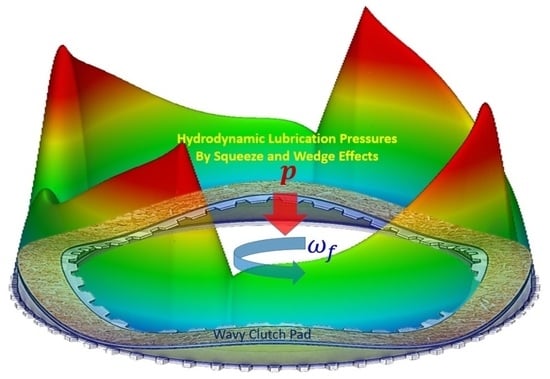
In addition to the squeeze film effect, hydrodynamic lubrication pressure can also be strongly generated if the friction surface has a gradient slope with respect to the steel plate under a high relative speed. Then, it generates the wedge effect (Equation (10)) under the hydrodynamic lubrication mechanism, whereas the flat surface of the friction pad does not. The wedge effect that is caused by the surface slope gradient of the wavy surface shape occurs more rigorously in the initial stage of engagement when the relative velocity is largest. The wavy model has a 4wavy shape around the friction pad surface (Figure 9), fast loading condition, and low viscosity and elastic modulus to manage positive μ–V characteristics. It can generate both squeeze and wedge effects more strongly in the initial stage of engagement than a flat surface. Therefore, it can also actively provide positive μ–V characteristics.
5. Results and Comparisons
Manipulation of material parameters of the friction pad and operating conditions results in various formations of hydrodynamic and contact pressures phyd and pc, respectively, particularly in the initial stage of engagement. A comparison of the reaction forces among the three computed models of the friction pad is shown in Figure 10. In the initial stage of engagement, a high hydrodynamic pressure enhances the frictional torque. Careful selection of material properties for the friction pad (modified base model) and geometrical shape of the friction pad (wavy model) provide high hydrodynamic pressures.
Further, the minimum film thickness of the lubricant between the friction pad and steel plate depends on the roughness level of the friction pad and geometrical shape (Figure 11). A rough surface can afford a thicker film. However, waviness can result in a relatively thin film due to the concentration of its contact geometry.
Relative velocity variation (Figure 12) indicates that the engagement period is influenced by the amount of generated frictional torque that comes from the combination of both material properties of the friction pad and operation conditions. In this study, the waviness of the friction pad resulted in faster engagement than the flat surface.
Transferred torques among the three models during the wet clutch engagement are shown in Figure 13. The base model exhibits a smooth change in frictional torque, whereas the other two models show gradually decreasing torques until the completion of engagement. At the moment of engagement completion, it shows a rooster-tail-like shape (Figure 13) that is directly influenced by the friction model constant of the mechanical contact, that is, C2. The equivalent frictional coefficient that is computed from the transferred total torque during the engagement using Equation (18) is shown in Figure 14a. At the moment of engagement initiation, frictional resistance is generated mostly from the squeeze effect of hydrodynamic lubrication until t = 0.05 s and then wedge effect of lubrication begins. Both squeeze and wedge effect play a major role with the maximum around t = 0.05 s in the modified base and wavy models (Figure 14b), whereas the base model has a smaller value of frictional torque due to hydrodynamic lubrication (Figure 13b). Figure 15 reveals that the film thickness decrease rate is much higher in the flat and 4wavy models due to the material softness and high permeability.
Hydrodynamic lubrication film pressures are developed according to the applied load mode, surface roughness, and material properties such as permeability and elasticity. They are shown in Figure 16 for the base model, modified base model, and wavy model. The fluid film pressures, Phyd, are compared at the same time, i.e., 0.5105 × 10⁻² s, after the commencement of loading. In addition, the maximum hydrodynamic pressure, Phyd_max, of each model is compared at its time of maximum developed value. The developed hydrodynamic pressures in the models have their own shapes and magnitudes according to the material properties of the friction pad and operating conditions. This means that a positive μ–V frictional mode is achievable in the wet clutch engagement through the development of a strong hydrodynamic pressure of the lubricant film. Many experimental works [1,2,3,5,7,9] that are compared with simple one-dimensional analysis of flat wet clutch engagement performance show good tendencies to our computational results of two-dimensional analysis. The present numerical results can provide more detail the lubrication mechanism in every area of wet clutch contact geometry.
6. Conclusions
In this study, torque transfer during the engagement of the wet clutch was studied with influencing parameters of the wet clutch friction pad material and operating conditions to achieve positive μ–V characteristics. A positive μ–V mode can be obtained by realizing a relatively high torque for enhancing the hydrodynamic lubrication effects in the initial stage of engagement. Moreover, the squeeze film effect can be actively utilized with soft elasticity, high permeability of the friction pad material, and fast loading mode to achieve a high reduction rate of film thickness . This leads to a relatively high torque in the initial engagement and can provide positive μ–V characteristics.
Further, the surface geometry of the friction pad can enhance the hydrodynamic lubrication effect. The waviness of the friction pad surface makes the hydrodynamic lubrication actively well performing due to the wedge effect of hydrodynamic lubrication with the lubrication film thickness gradient . It leads to an enhancement in the positive μ–V characteristics in the wet clutch engagement.
The computational work conducted in this study found that a positive μ–V friction mode in the wet clutch system can be realized by the manipulation of the material properties of the friction pad, operating conditions, and geometrical surface design to reduce shudder, particularly in the initial stage of engagement when the relative sliding velocity is high.
Funding
This research was funded by the Basic Science Program through the National Research Foundation (NRF), Grant No.: 2018R1D1A1B07043950.
Data Availability Statement
The author will provide data (except Figure 16) upon reasonable request.
Acknowledgments
This work was supported by the Basic Science Program through the National Research Foundation (NRF), Grant No.: 2018R1D1A1B07043950.
Conflicts of Interest
The author declares no conflict of interest.
Nomenclature
| A | clutch pad area (m2) |
| Ac | area of contact per unit normal area (m2) |
| C1, C2 | curve fitting constant of friction coefficient (-) |
| Cf | equivalent friction coefficient (-) |
| d | thickness of friction pad (m) |
| E1 | elastic modulus of steel plate (N/m2) |
| Ec | elastic modulus of friction pad (N/m2) |
| fc | friction coefficient (-) |
| dynamic friction coefficient (-) | |
| static friction coefficient (-) | |
| fluid film thickness (m) | |
| h0 | initial film thickness (m) |
| hT | average film thickness (m) |
| I | mass moment of inertia (Kgm2) |
| Nw | waviness number of friction pad |
| pa | applied hydraulic pressure on the clutch pad (Pa) |
| pc | contact pressure (Pa) |
| ph | hydrodynamic fluid film pressure (Pa) |
| p0 | final applied hydraulic pressure on the clutch pad (Pa) |
| Q: | volume flow rate per unit cross-sectional area (m/s) |
| r | coordinate in radial direction (m) |
| Ra | surface roughness (m) |
| Ri | inner radius of clutch pad (m) |
| Ro | outer radius of clutch pad (m) |
| Tc | frictional torque by asperity contact (Nm) |
| Th | frictional torque by hydrodynamic fluid film (Nm) |
| s | slip ratio (-) |
| t | time (s) |
| t0 | delay time of applied load (s) |
| fluid velocity in x direction (m/s) | |
| fluid velocity in y direction (m/s) | |
| v1 | non-porous steel plate velocity (m/s) |
| vB | fluid velocity at the interface in Darcy flow (m/s) |
| w | amplitude of waviness (m) |
| W | applied load (N) |
| x | coordinate in x direction (m) |
| y | coordinate in y direction (m) |
| z | coordinate in axial direction (m) |
| slip coefficient (-) | |
| asperity tip radius (m) | |
| compressive strain of friction pad | |
| number of asperities per unit area (1/m2) | |
| coordinate in circumferential direction | |
| permeability (m2) | |
| viscosity (Pas) | |
| Poisson ratio of friction pad | |
| Poisson ratio of steel plate | |
| Beavers and Joseph slip factor | |
| density (kg/m2) | |
| rms roughness (m) | |
| pressure flow factors in radial direction | |
| pressure flow factors in circumferential direction | |
| shear stress factor | |
| shear stress factor | |
| dimensionless relative velocity | |
| steel plate velocity (rad/s) | |
| friction pad velocity (rad/s) |
References
- Gao, H.; Barber, G.C. Engagement of a rough, lubricated and grooved disk clutch with a porous deformable paper-based friction material. Tribol. Trans. 2002, 45, 464–470. [Google Scholar] [CrossRef]
- Wenbin, L.; Jianfeng, H.; Jie, F.; Liyun, C.; Chunyan, Y.; Wenjing, W. Simulation of the engagement of carbon fabric wet clutch: Analytical and experimental comparison. Tribol. Int. 2015, 90, 502–508. [Google Scholar] [CrossRef]
- Zhang, Z.; Zou, L.; Liu, H.; Chen, Y.; Zhang, B. Simulation and modeling of dynamic friction coefficient of wet clutch engagement. Int. J. Automot. Technol. 2022, 23, 125–134. [Google Scholar] [CrossRef]
- Li, M.; Khonsari, M.; Yang, R. Dynamics analysis of torsional vibration induced by clutch and gear set in automatic transmission. Int. J. Automot. Technol. 2018, 19, 473–488. [Google Scholar] [CrossRef]
- Ogawa, H.; Hayashi, E.; Yoshida, O.; Hayakawa, Y.; Kuroyanagi, T.; Ishikawa, K.; Takabayashi, H.; Maruo, K.; Fujii, T. Mechanism of shudder phenomena in torque converter and system simulation model. SAE Trans. Sect. 3 J. Engines 2007, 116, 324–332. [Google Scholar]
- Berger, E.J.; Sadeghi, F.; Krousgrill, C.M. Torque transmission characteristics of automatic transmission wet clutches: Experimental results and numerical comparison. Tribol. Trans. 1997, 40, 539–548. [Google Scholar] [CrossRef]
- Davis, C.L.; Sadeghi, F.; Krousgrill, C.M. A simplified approach to modeling thermal effects in wet clutch engagement: Analytical and experimental comparison. J. Tribol. 2000, 122, 110–118. [Google Scholar] [CrossRef]
- Cho, J.; Lee, Y.; Kim, W.; Jang, S. Wet single clutch engagement behaviors in the dual-clutch transmission system. Int. J. Automot. Technol. 2018, 19, 463–472. [Google Scholar] [CrossRef]
- Yang, Y.; Lam, R.C.; Fujii, T. Prediction of torque response during the engagement of wet friction clutch. SAE Trans. 1998, 107, 1625–1635. [Google Scholar]
- Lam, R.C.; Chavdar, B.; Newcomb, T. New generation friction materials and technologies. SAE Tech. Pap. 2006, 2006-01-0150. [Google Scholar] [CrossRef]
- Gao, H.; Barber, G.C.; Shillor, M. Numerical simulation of engagement of a wet clutch with skewed surface roughness. J. Tribol. 2002, 124, 305–312. [Google Scholar] [CrossRef]
- Gao, H.; Barber, G.C. Microcontact model for paper-based wet friction materials. J. Tribol. 2002, 124, 414–419. [Google Scholar] [CrossRef]
- Eguchi, M.; Yamamoto, T. Shear characteristics of a boundary film for a paper-based wet friction material: Friction and real contact area measurement. Tribol. Int. 2005, 38, 327–335. [Google Scholar] [CrossRef]
- Fei, J.; Li, H.; Huang, J.; Fu, Y. Study on the friction and wear performance of carbon fabric/phenolic composites under oil lubricated conditions. Tribol. Int. 2012, 56, 30–37. [Google Scholar] [CrossRef]
- Natumeda, S.; Miyoshi, T. Numerical simulation of engagement of paper based wet clutch facing. J. Tribol. 1994, 116, 232–237. [Google Scholar] [CrossRef]
- Jang, J.Y.; Khonsari, M.M. Thermal characteristics of a wet clutch. J. Tribol. 1999, 121, 610–617. [Google Scholar] [CrossRef]
- Jang, J.Y.; Khonsari, M.M.; Maki, R. Three-dimensional thermohydrodynamic analysis of a wet clutch with consideration of grooved friction surfaces. J. Tribol. 2011, 133, 011703. [Google Scholar] [CrossRef]
- Berger, E.J.; Sadeghi, F.; Krousgrill, C.M. Finite Element Modeling of Engagement of Rough and Grooved Wet Clutches. J. Tribol. 1996, 118, 137–146. [Google Scholar] [CrossRef]
- Berger, E.J.; Sadeghj, F.; Krousgrill, C.M. Analytical and numerical modeling of engagement of rough, permeable, grooved wet clutches. J. Tribol. 1997, 119, 143–148. [Google Scholar] [CrossRef]
- Li, M.; Khonsari, M.M.; McCarthy, D.M.C.; Lundin, J. Parametric analysis for a paper-based wet clutch with groove consideration. Tribol. Int. 2014, 80, 222–233. [Google Scholar] [CrossRef]
- Beavers, G.S.; Joseph, D.D. Boundary conditions at a naturally permeable wall. J. Fluid Mech. 1967, 30, 197–207. [Google Scholar] [CrossRef]
- Greenwood, J.A.; Williamson, J.B.P. Contact of Nominally Flat Surfaces. Proc. R. Soc. Lond. Ser. A 1966, 295, 300–319. [Google Scholar]
- Patir, N.; Cheng, H.S. Application of average flow model to lubrication between rough sliding surfaces. ASME J. Lubricat. Technol. 1979, 101, 220–230. [Google Scholar] [CrossRef]
- Patir, N.; Cheng, H.S. An average flow model for determining effects of three-dimensional roughness on partial hydrodynamic lubrication. ASME J. Lubricat. Technol. 1978, 100, 12–17. [Google Scholar] [CrossRef]
Figure 1.
Fluid film behavior in the porous wet clutch contact.

Figure 2.
Wet clutch engagement with fluid film and elastic deformation of friction pad.

Figure 3.
Reaction forces due to mechanical contact and hydrodynamic lubrication against applied pressure.
Figure 3.
Reaction forces due to mechanical contact and hydrodynamic lubrication against applied pressure.

Figure 4.
Frictional torques due to mechanical contact with the curve-fitting model, Equation (14), and shear resistance due to hydrodynamic lubrication during the engagement with the base model.
Figure 4.
Frictional torques due to mechanical contact with the curve-fitting model, Equation (14), and shear resistance due to hydrodynamic lubrication during the engagement with the base model.

Figure 5.
Wet clutch pad contact with steel plate for the base model.

Figure 6.
Applied pressure on the friction pad and film thickness variation during the engagement period.
Figure 6.
Applied pressure on the friction pad and film thickness variation during the engagement period.

Figure 7.
Relative velocity ( variation during the wet clutch engagement.

Figure 8.
Equivalent friction coefficient and squeeze film effect as a function of sliding velocity and time during the wet clutch engagement. (a) Equivalent friction coefficient, Equation (18), according to the relative velocity ( during the wet clutch engagement. (b) Squeeze film effect as a function of sliding velocity and (c) time during the wet clutch engagement. (d) Relative velocity ( during the wet clutch engagement.


Figure 9.
Wavy surface of friction pad (wavy model).

Figure 10.
Comparison of reaction forces among the three computed models.

Figure 11.
Minimum film thickness variations during the engagement.

Figure 12.
Relative velocity variations during the engagement.

Figure 13.
(a) Transferred total torques and (b) hydrodynamic and mechanical contact variations during the engagement.
Figure 13.
(a) Transferred total torques and (b) hydrodynamic and mechanical contact variations during the engagement.

Figure 14.
(a) Total transferred torques and (b) hydrodynamic and mechanical contact variations during the engagement.
Figure 14.
(a) Total transferred torques and (b) hydrodynamic and mechanical contact variations during the engagement.

Figure 15.
Comparison of film thickness change rate versus time during the engagement.

Figure 16.
Hydrodynamic pressure comparisons of the three models at the same time, and maximum values during the engagement (see Figure 10 for Phyd_max).
Figure 16.
Hydrodynamic pressure comparisons of the three models at the same time, and maximum values during the engagement (see Figure 10 for Phyd_max).


Table 1.
Parameters of the wet clutch pad and operating conditions for the base model.
| Relative friction pad speed | 1500 rpm |
| Final applied pressure | 6.5 bar |
| Engagement delay time | 0.01 s |
| Initial film thickness | 25.4 × 10⁻⁶ m |
| Viscosity | 7.24 mPas |
| Slip coefficient s | 0.2 |
| Permeability | 5.0 × 10⁻¹⁵ m2 |
| Elastic modulus | 50.0 × 10⁸ N/m2 |
| Asperity density | 3.0 × 10⁶ m−2 |
| Asperity tip radius | 5.0 × 10⁻⁴ m |
| Roughness | 5.4 × 10⁻⁶ m |
| Inner radius | 68.83 × 10⁻³ m |
| Outer radius Ro | 91.50 × 10⁻³ m |
| Pad thickness d | 7.50 × 10⁻⁴ m |
| Inertia of clutch I | 0.11 kgm2 |
| Friction model constants | C1 = 0.13, C2 = 0.002175 |
Table 2.
Material properties and operating conditions for the wet clutch models.
| Parameters | Base Model | Modified Base Model | Wavy Model |
|---|---|---|---|
| Shape of friction pad | flat | ← | 4wavy |
| Relative rotational speed | 1000 rpm | ← | ← |
| Final applied pressure | 6.5 bar | ← | ← |
| Engagement delay time | 0.01 s | 0.005 s | 0.002 s |
| Initial film thickness | 25.4 × 10⁻⁶ m | ← | ← |
| Viscosity | 7.24 mPas | ← | 6.51 mPas |
| Slip coefficient | 0.2 | ← | ← |
| Permeability | 5.0 × 10⁻¹⁵ m2 | 1.0 × 10⁻¹³ m2 | 1.5 × 10⁻¹³ m2 |
| Elastic modulus | 50.0 × 10⁸ N/m2 | 35.0 × 10⁷ N/m2 | 20.0 × 10⁷ N/m2 |
| Asperity density | 3.0 × 10⁶ m−2 | ← | ← |
| Asperity tip radius | 5.0 × 10⁻⁴ m | ← | ← |
| Roughness | 5.4 × 10⁻⁶ m | 4.5 × 10⁻⁶ m | 4.5 × 10⁻⁶ m |
| Inner radius | 68.83 × 10⁻³ m | ← | ← |
| Outer radius | 91.50 × 10⁻³ m | ← | ← |
| Pad thickness | 7.50 × 10⁻⁴ m | ← | ← |
| Inertia of clutch | 0.11 kgm2 | ← | ← |
| Friction model constants | C1 = 0.13, C2 = 0.002175 | C1 = 0.13, C2 = 0.002175 | C1 = 0.13, C2 = 0.002175 |
Publisher’s Note: MDPI stays neutral with regard to jurisdictional claims in published maps and institutional affiliations. |
© 2022 by the author. Licensee MDPI, Basel, Switzerland. This article is an open access article distributed under the terms and conditions of the Creative Commons Attribution (CC BY) license (https://creativecommons.org/licenses/by/4.0/).
Share and Cite
MDPI and ACS Style
Jang, S. Manipulating Frictional Performance of Wet Clutch Engagement through Material Properties and Operating Conditions. Lubricants 2022, 10, 225. https://doi.org/10.3390/lubricants10090225
AMA Style
Jang S. Manipulating Frictional Performance of Wet Clutch Engagement through Material Properties and Operating Conditions. Lubricants. 2022; 10(9):225. https://doi.org/10.3390/lubricants10090225
Chicago/Turabian StyleJang, Siyoul. 2022. "Manipulating Frictional Performance of Wet Clutch Engagement through Material Properties and Operating Conditions" Lubricants 10, no. 9: 225. https://doi.org/10.3390/lubricants10090225
Note that from the first issue of 2016, this journal uses article numbers instead of page numbers. See further details here.